|
1. Use the
screwdriver to
unscrew and open the bottom cover to
unscrew and open the bottom cover ,
insert the insulation plug ,
insert the insulation plug 〔 〔 the side
with a red the side
with a red
line must be facing up and the opposite side with the two
raised notches must be facing down) into the plug socket on the
top cover  before
installing the battery, otherwise the alarm will be immediately
triggered. Insertion of the insulation plug before
installing the battery, otherwise the alarm will be immediately
triggered. Insertion of the insulation plug
is directional
( one side with a
red line and the other with two raised notches), please
ensure that it is inserted correctly.


NOTE
: Do not insert the burglar alarm plug into
the plug socket,
otherwise the bottom coverand
top cover into
the plug socket,
otherwise the bottom coverand
top cover cannot be disassembled or reassembled.

2. Install the battery into
the battery holder into
the battery holder (Make
sure the polarity is correct). (Make
sure the polarity is correct).
3. Test the basic functions: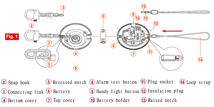
(1). Alarm Siren :Test 1 : Press the red button (The
alarm and handy light will be activated at the same time). (The
alarm and handy light will be activated at the same time).
Test 2 : Remove the insulation plugfrom
the plug socketand
reinsert it.
(2). Handy Light: Press button . .
4. Place the connecting link of
the snap hook of
the snap hook into
the recessed notch into
the recessed notch inside
the bottom cover. inside
the bottom cover.
5. Once reassembled and the alarm device is upside down, the side marked with a red
line of the insulation plug should be
facing up.. 
NOTE : The
insulation plug can be pulled completely out of the plug socket by
tugging on the loop strap and can be
reinserted by pushing it back in.
TOP
|


